Four spring-loaded probes covering the pitch range most in-circuit and functional test fixtures are built around — 1.00 mm (.039) through 2.54 mm (.100). Same body concept, different pitch, stroke and current.
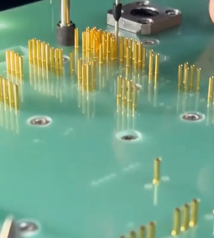
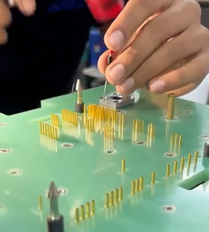
Every figure below is taken from the manufacturer's own catalogue. These are design values, not third-party test reports.
| Field | LH-061 | LH-078 | LH-102 | LH-137 |
|---|---|---|---|---|
| Minimum centers | 1.00 mm (.039) | 1.27 mm (.050) | 1.91 mm (.075) | 2.54 mm (.100) |
| Working stroke | 3.0 mm (.118) / 4.3 mm (.169) | 4.3 mm (.169) | 4.3 mm (.169) | 4.3 mm (.169) |
| Maximum stroke | 3.9 mm (.153) / 6.35 mm (.250) | 6.35 mm (.250) | 6.35 mm (.250) | 6.35 mm (.250) |
| Spring force options | 1.0 N (3.6 oz) | 1.0 / 1.5 / 2.0 N (3.6 / 5.4 / 7.2 oz) |
1.0 / 1.5 / 2.0 / 2.8 N (3.6 / 5.4 / 7.2 / 10.1 oz) |
1.0 / 1.5 / 2.0 / 2.5 / 3.0 N (3.6 / 5.4 / 7.2 / 9.0 / 10.8 oz) |
| Current rating | 1–3 A | 1–3 A | 3–4 A | 3–5 A |
| Contact resistance | ≤ 20 mΩ | ≤ 20 mΩ | ≤ 20 mΩ | ≤ 20 mΩ |
| Operating temperature | −40 °C to +80 °C | −40 °C to +80 °C | −40 °C to +80 °C | −40 °C to +80 °C |
| Plunger | Beryllium copper or SK4 tool steel, gold plated over hard nickel | |||
| Barrel | Phosphor bronze, gold plated | |||
| Spring | Music wire, gold plated | |||
A probe is only half of a contact system. These are the LHR receptacle codes the factory lists against each series.
| Probe series | Receptacle codes we publish | INGUN equivalent |
|---|---|---|
| LH-061 | LHR061-4W · LHR061-4C · LHR061-4DX | None published |
| LH-078 | LHR078-08E · LHR078-08G · LHR078-08HE · LHR078-08DX | KS-050 E08 → LHR078-08DX |
| LH-102 | LHR102-4W · LHR102-4S · LHR102-4FL | KS-075 30G → LHR102-4S KS-075 47G → LHR102-4W / 4FL |
| LH-137 | LHR137-4W · LHR137-4S · LHR137-4FL | KS-100 30G → LHR137-4S KS-100 47G → LHR137-4W / 4FL |
| PCB-series receptacles | LHPR102-3S · LHPR102-3W | KS-001 30G → LHPR102-3S KS-001 47G → LHPR102-3W |
| LH-200 | LHR200-4S | KS-003 30G → LHR200-4S |
| LH-236 | LHR236-4S | KS-004 30G → LHR236-4S |
For 1.00 mm (.039) centers where the fixture is dense and the board will not take a heavy spring load. Single force option, 1.0 N.
1.27 mm (.050) is the most common ICT grid. Three force options, four receptacle styles including the -08DX variant.
1.91 mm (.075) centers with a 3–4 A rating. Four force options up to 2.8 N.
2.54 mm (.100) centers, 3–5 A, and the widest force range of the four — five options from 1.0 N to 3.0 N.
Where the fixture is shallow, these series are also built short-body under the LHD prefix — for example LHD-078 C05 050 1.5N: series 078, C05 round tip, 1.5 N spring. Same numbering logic as the tables above; confirm the length code against your stack height.
Send the footprint pitch, the component you are probing and the fixture stack height. The factory selects the series; we do not guess from a part number.
Type GKS 100 307 150 A3000 and get the LH part, using the manufacturer's own published series, tip, force and receptacle rules — with all 17 confirmed pairs shown alongside.
66 series in total across the LH catalogue.
ICT and FCT general-purpose spring probes.
Non-springing wire probes and tungsten micro-needles. Quoted from the drawing, one model at a time.